Of cores 2 3 4 7 12 19 27 37 2 3 4 7.
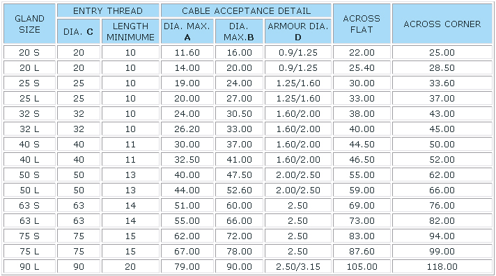
Pdf armoured cable gland size chart.
The glands are also available with a loose cone.
Cable gland selection chart.
What s more it will also facilitate the fast accomplishment of your installation.
Resistant t o salt water weak aci d alco hol o il grease and common solvency.
The popular steel wire armour cable gland consists of four parts.
Cable gland size tables are provided below for general guidance however reference should be made to the relevant british standard or gland supplier.
Pg7 cable gland with the cable clamping range 3 6 5mm that means the electrical cable diameter size must be in this range otherwise you should change another size to match it.
Ag mm thread length gl mm spanner size mm packing pcs bag pg7 pg9 pg11 pg13 5 pg16 pg19.
Below is a reference chart for dictating the size of armoured cable gland required for the size of armoured cable that is being used cable size mm 1 core.
The claws and seals of excellent design can hold cable firmly and have a wider cable range.
The outer nut the inner the cable gland bush with rotary cone and the locknut as shown below.
Pg type cable gland code n o cable range mm thread o d.
Cable gland chart cable gland selector cable type conductor area mm2 1 5 2 5 4 6 10 16 25 35 50 70 95 120 150 185 240 300 no.
Swa cable gland chart.
Cleat selection chart swa gland size chart bw and cw glands cable cleat size chart nominal cross number of cores sectional area mm2 1 5 20s 20s 20s 20s2020 25s 20s2532 32 2 5 20s20s 20s 2020 25s 25s25 32 32 40 4 0 20s20 2020 25s 3232 32 40 6 0 2020 20 10 0 2020 25s.

